Wang 360E Technology
Electronics
Discrete diode-transistor circuits, hardwired logic.
Architecture, Memory & Speed
- 10 displayed digits, 4 hidden added precision diagis, 1 sign digit and 1 decimal position digit = 16 digits word
- Digits encoded as 4-bit BCD, digit-serial processing over 4-bit internal bus
- Core memory, 4 registers x 16 digits x 4 bits = 256 cores
Construction
The 300 series machines were presented as a briefcase-sized electronics unit and a desktop keyboard/display unit. More advanced desktop units could incorporate some intelligence, particularly the means to memorise keystroke sequences, and this allowed extended functions such as keyboards with automatic replay of sequences for trigonometric functions.
The keyboards used the same utilitarian short travel microswitch buttons as the LOCI machines. The keyboard electronics consist of a diode encoding array for keystrokes and decoders for display digits and digit positions.
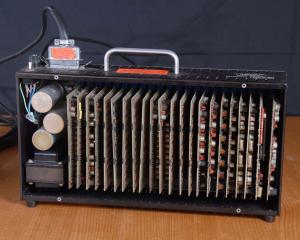
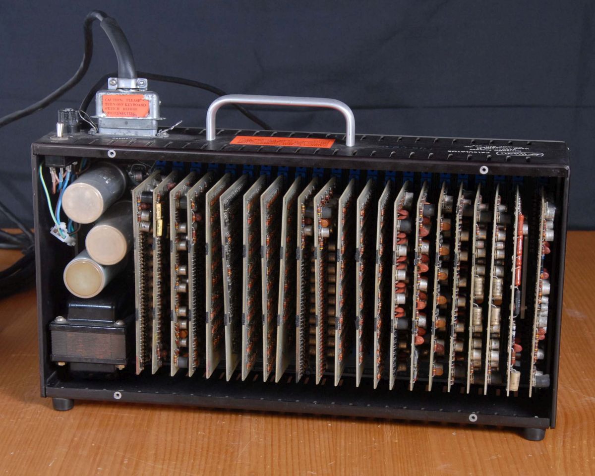
The electronics units were constructed with a backplane that plugged many smallish double-sided boards. This arrangement may have reflected Dr Wang’s original 1950s development of a family of custom electronic logic building blocks and indeed Wang calculator circuit boards are always known as “Logiblocs” in Wang literature. The arrangement may have offered some advantage of modularity and field repair by simple board swapping but over time this has been offset by deterioration in the many edge connector contacts, which Wang always declined to gold plate. Poor electrical connections are now a source of problems in old machines and some care is required in their treatment, so as to avoid further degrading the contacts.
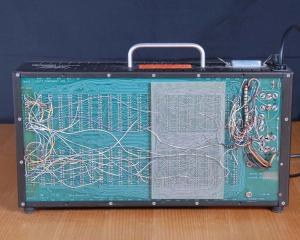
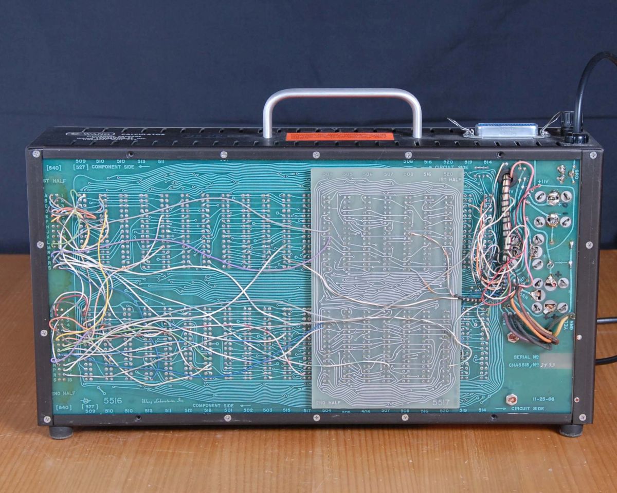
For those struggling to trace signals across this backplane, an interactive spreadsheet is available in the Data&Links section.
The power supply is a basic transformer design, the logic levels are 0v and -11v with a +11v bias and +250v Nixie supply. There is no regulation on these supplies but a regulated +/- 5.1v level is developed locally for the core memory and master clock.