HP 5360A Technology

There are three calculation registers and four storage registers, all implemented with TTL flip-flop shift registers. This is a more computer-like design (similar to the Wang LOCI) which is faster and in some respects simpletr, but requires more electronics. Calculator designers of the 1960s who were conscious of price used core or delay line memory to store most or all of the working registers thus reducing the amount of expensive electronic logic. The 5360A designers were unlikely to have been constrained by cost and were able to take the more direct and higher-performing solution of placing all functions directly into electronic logic.
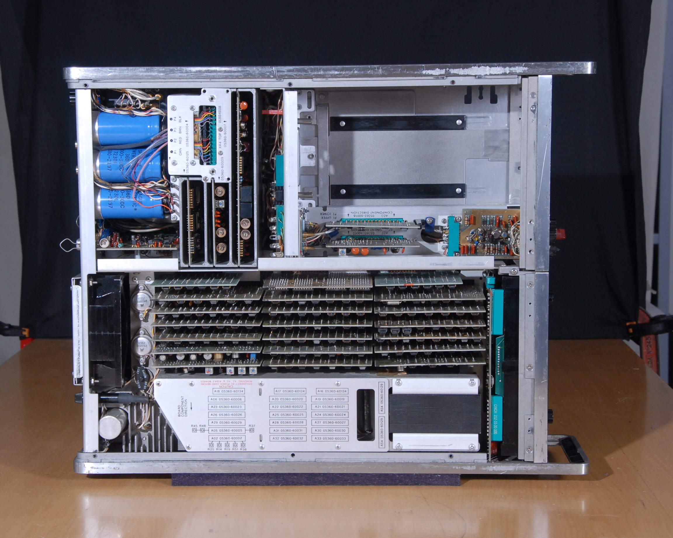
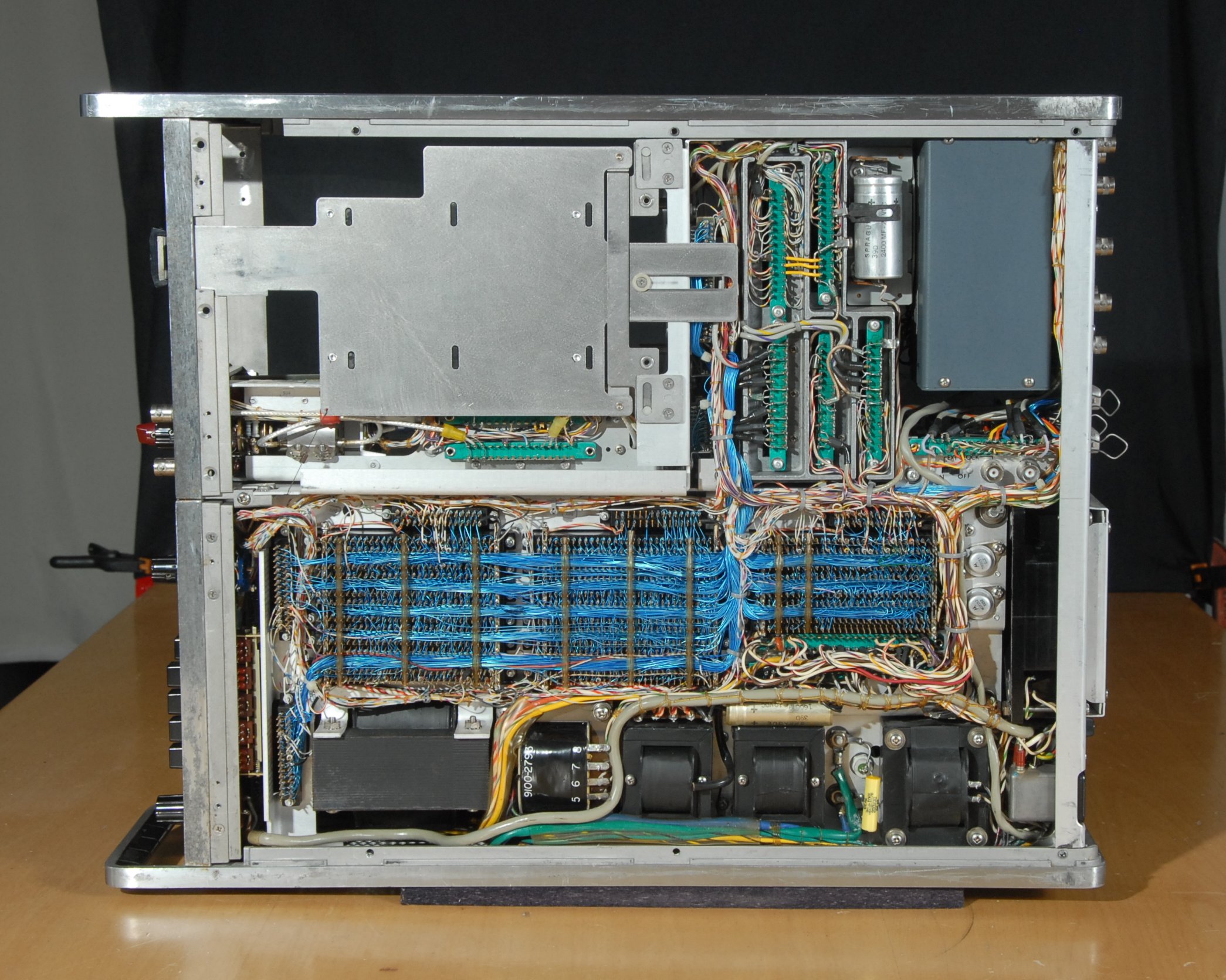
There was clearly a substantial budget for basic construction. The overall chassis is highly engineered and the plug-in bays have elaborate guides and latches to ensure accurate mating of multiple connectors. The PCBs of the input stage are housed in separate pockets of an elaborate metal casting which must provide electrical shielding and thermal stability for the signal input and processing boards. The master oscillator is housed in its own temperature-controlled package beside the input stage. Interconnections are well-dressed and liberal use is made of coaxial cables.
The instruction set for the calculation engine is more microcode-like than programmable calculator-like, which reflects the primary purpose of the calculation engine in support of the measurement and display of time and frequency. The microcode is 5 bits wide which gives 32 instructions:
- 0x00
- 0x01
- 0x02 Call subprogrm stored in the Input Module
- 0x03 Call subprogram stored in the Plug-in Module
- 0x04
- 0x05 Square Root of a-register
- 0x06 Call Self-Test from mainframe ROM
- 0x07 Call Calibrate from mainframe ROM
- 0x08 Display value in a-register
- 0x09 Multiply a-register by 10 (decimal)
- 0x0A Add a- and b-registers
- 0x0B Subtract a-register from b-register
- 0x0C Reciprocal of a-register
- 0x0D Load number into a-register
- 0x0E Divide b-register by a-register
- 0x0F Multiply b-register by a-register
- 0x10 Exchange a-register and S1-register
- 0x11
- 0x12 Copy S1- to a-, and a- to b-
- 0X13
- 0x14 Double a-register (add a- to a-)
- 0X15 Exchange a- and b-
- 0x16 Clear a-register to 0
- 0x17 Copy a- to b-register
- 0x18 Exchange a-register with S2-register
- 0x19
- 0x1A Copy S2- to a-, and a- to b-
- 0x1B
- 0x1C Divide a-register by 10 (decimal)
- 0x1D Exchange a- and c-registers
- 0x1E Clear a-, b- and c-registers to 0
- 0x1F Copy c- to a- and a- to b-register
It is clear that the 5360A was aimed at the highest standards. The calibration manual requires that the machine be switched on for 24 hours before any adjustments and to pass test it must be stable to within 3 parts in 10 million.