Friden EC-130 Calculator Technology
Electronics
First-generation diode-transistor logic.
Architecture, Memory & Speed
- 14 displayed digits, 1 sign digit and one decimal position digit = 16 digit word
- Digits encoded as a unary (not binary) bit-stream where each digit has a ten-pulse window and the digit’s value is represented by the position of pulses within that window.
- A magnetostrictive wire delay line provides storage for a total of 6 registers. The delay time is approx 5 mSec and the smallest significant interval is the 3uSec ‘bit time’.
- 666 kHz master clock
Construction
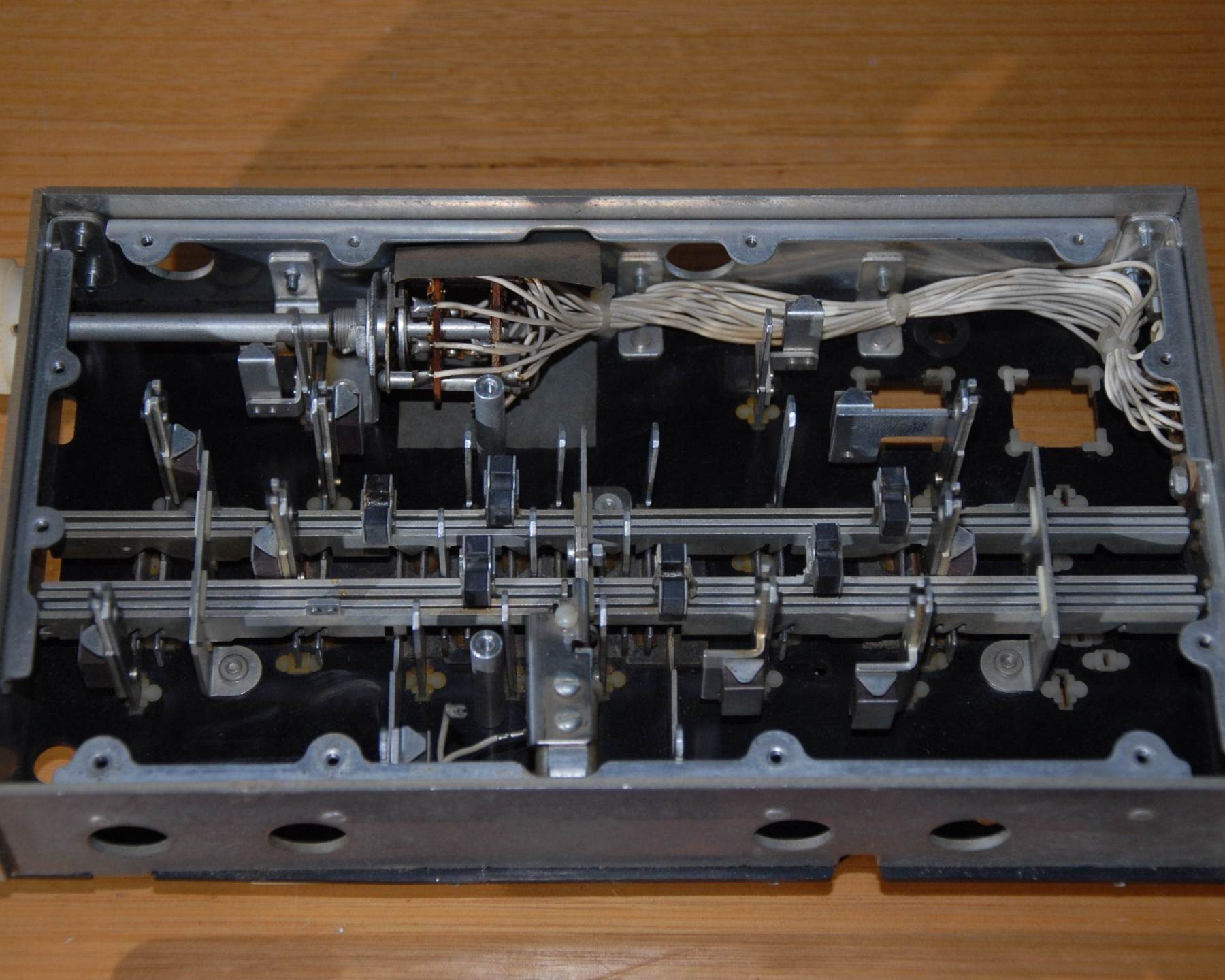
Friden’s design and metalworking skills are showcased in the four intricate castings that form the main chassis and the streamlined sheetmetal upper cover. The pieces fold, slide and clip together with just a few screws for final security. There is a secret lock-out that can prevent the power switch from operating, its use requires some technical expertise and it’s not clear what the anticipated use was. The secret may be discovered from the photographs, this is left as a puzzle for visitors.
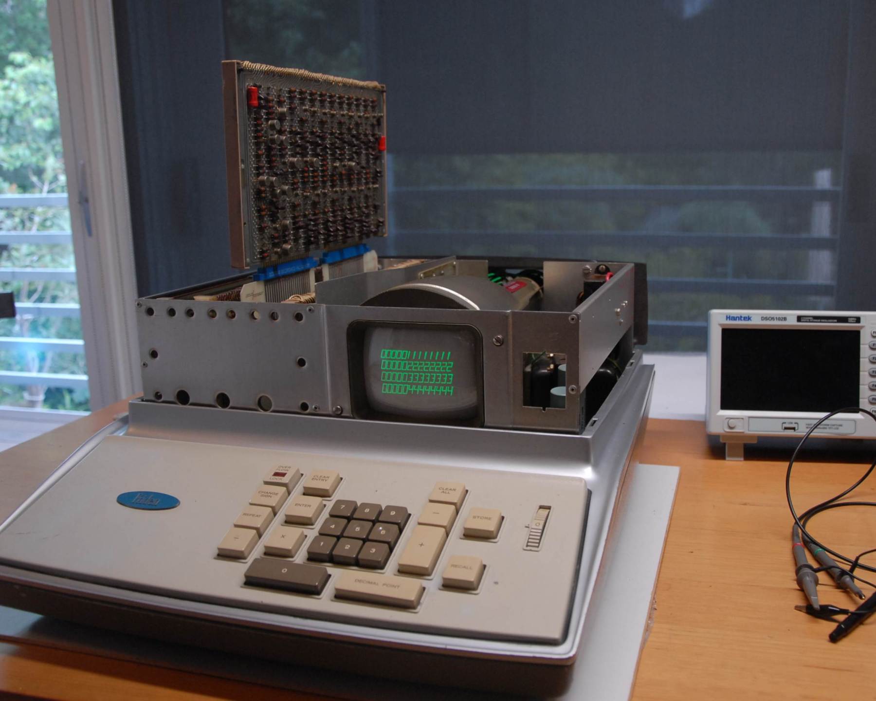
The electronics cage is a separate subassembly and is divided into two bays with a metal separator that shields the low voltage logic from the high voltage electrostatic CRT (and vice versa). The logic bay houses four plug-in units each composed of two double sided boards that are connected by a spine of jumper wires. The edge connectors are thoughtfully offset to different distances for each module to eliminate insertion errors. This is a nice contrast to the Wang 362SE where any of the 32 identically-sized boards can be plugged into any of the 32 backplane slots! The EC 130 backplane interconnect is a circuit board and there are fat copper busbars for power distribution, the likes of which I have not seen in any other calculator. The second bay in the electronics cage houses the multi-primary mains transformer and the low voltage power supply with series-pass regulators producing +6v and -12v while a big zener mounted on the rear heatsink produces -80v. The 3kV CRT anode voltage is generated by a voltage multiplier that is fed from a dedicated transformer that is in turn driven by its own oscillator. The CRT is mounted above the high voltage generator within a mu-metal shroud.